I am playing with LEDs for few month and during that time some little projects were born, but now I need a system to handle the logical part and the power distribution. I simply just can’t use an Arduino board, or any other development board: I need a proper power handling embedded in a small space, all in one PCB, with some particularly high power requirements. And being Arduino compatible. This is Lino.
It will be used to power up the Glighter-S modules in a compact fashion, finally reaching something similar to a complete lighting working system. What is important here, is that we have 255 combination per each color, plus an algorithm to emulate in RGB and pure white combination to generate pastel colors or shades of white. With such assumption, I do not use any LUT but instead I generate the color according to the HTML encoding executed on the Lino microcontroller.
Project purpose and board review
This board is designed to power up any power LED, motor and/or anything which requires up to 10W and can be controlled in PWM. Lino supports in hardware the control through physical, glitch filtered, inputs like buttons and encoders.
In the picture below is shown the board with its main interfaces:

More protocols are supported onboard, like I2C and UART (real or through USB emulation). With the proper firmware running on Lino, terminal commands are supported using the serial protocol, connected with the Atmega (the main MCU) mainly in two ways: with USB through an emulated terminal, or directly with the microcontroller’s UART, supporting then any communication with a serial device, like the ESP8266 and with no additional circuitry, since everything is working at 3.3V.
Since this board can communicate using UART or I2C, this setup is scalable, making it capable to drive more Lino boards connected with each other.
Board characteristics: the union of Atmel and Microchip in practice
Here is shown the main blocks of the board. It is a kind of celebration of the acquisition of Atmel from Microchip. It is used an Atmega328P microcontroller and the Microchip MCP2200 USB to Serial converter instead of the FTDI, which instead would costs truly a lot.
Below, the block diagram of the project and a picture which shows where physically things were arranged on the board:


Everything is almost self-explaining. Briefly, the HMI (Human-Machine Interface) can support a single Encoder with an integrated button to minimize the commands and user interface complexity, but with firmware mods can be anything else.
The controller core is the Atmega328P, which is used to keep an Arduino compatibility. With the low cost and well supported Microchip MCP2200 I can obtain a neat working system interfaced with any PC or serial device: in fact I have also a pure serial connector, with 3.3V voltage swings. For example it can talk with the famous ESP8266 with no additional circuitry.
A bit of more explanation is instead necessary for clarify the power handling.
Dynamic power source selection
The backbone of this system is the dynamic power handling. When powered from an external supply, up to 10W can be provided to the load, while can be still controlled from the USB port. If this supply is not present, is still possible to drive the board using the USB power, which allows up to 2.5W.
The selection is performed by the MCU (green dashed line in pictuire below), while a default safe state is kept when the MCU is not driving the switch. All the voltages are monitored, in order to allow the firmware to make the right selection. The priority of the source selection is given to the external power source.

The USB power is limited, since this board can be used directly connected to a PC, able to provide, normally, no more than 2.5W per USB port. Therefore, to use the entire power capability, an external power supply shall be used.
Due to the extremely high input voltage range, the power source selection is achieved in the firmware while the hardware is fully protected against misbehaviours and short circuits. After all, it is a personal project and burning a board is tedious and I can’t afford this, prevention is better. As also in professional environments, anyway.
Below just a brief of the supply characteristics:
| Electrical characteristics | Min | Max |
| Input voltage | 3.3V | 20V |
| Maximum supported power (USB only) | 2.5W | |
| Maximum supported power (Power Jack) | 10W | |
| Maximum supported power (Power Jack + USB) | 10W |
Source selection logics
The main power supply shall be capable to provide the total power required from the load. If this supply voltage is above the minimum required of around 3V, Lino is powered up and will source from the main supply. If the USB is present, the MCU can chose from where source the power. If the main supply is lower than 3V and the USB is present and the USB is present, the power is absorbed from the USB cable, otherwise the voltage would be insufficient.
Since the USB it is used to exchange the USB Data, it is usually connected to a device that cannot provide more than 500mA per USB port, therefore the power delivered to the load shall be reduced down to 2.5W using the firmware (in this particular case, by reducing the duty cycle of the PWM which drives the load).
Some quick results for the smoke test
Here are posted some pictures of the very initial setup, containing:
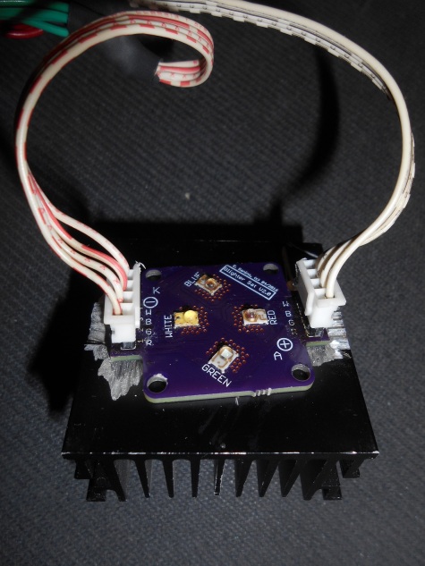
- 4 Luxeon Rebel LEDs on a satellite PCB
- An harvested power supply with >10W
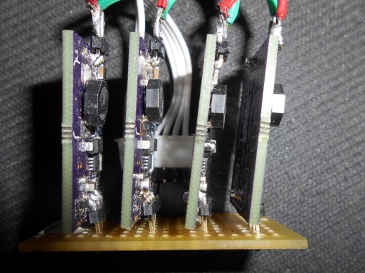
- 4 Glighter-S LED drivers
- The Lino board
Here the satellite PCB attached to an heatsink, estimated to be more than double of required dissipating capacity, attached with thermal tape:
Each pair of wire goes to the Glighter-S drivers:
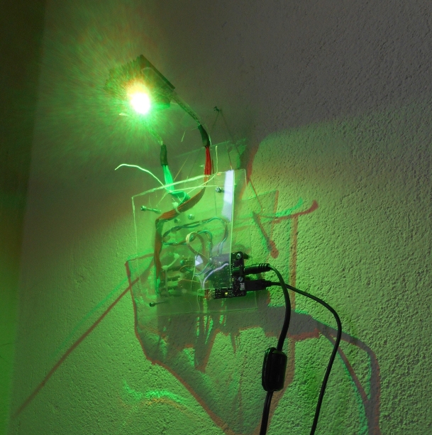
Where the complete “air-wire” setup looks like this:
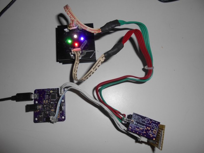
In this last picture Lino conveys the USB power to the LEDs, therefore the firmware detects the source of power, reducing the output to not exceed 2.5W – there is not power delivery negotiation, therefore even if the USB can deliver more ower, it will still be topped to 2.5W.
To use the full power, an external wall adapter is connected to the jack, turning on the desired LED or color (throught serial communication):
Next steps
The implementation of a proper firmware is on the “never-ending” to-do list. The communication protocol has been defined, as long as other details, which will be released open-source when finished.
The test loads (basiclly, the LEDs) are described a bit more in details in this article. Also, the hardware was a first attempt, hence it is just a proof of concept protocol, to learn what are the difficulties faced even when design such a simple board. And I have to say, just this attempt was already very constructive.

2 thoughts on “Lino Project”