It has been a while since the last LED related article. Was experimented the linear current source, its pros and cons and the field of application. Now arises the need of a small version, handling the same high power, things that are contrapposed in the linear regulator. I need something that I can bring with me, connecting a bit of everywhere, potentially. Heatsinks were expensive, heavy and it is impossible to cover the entire voltage range without huge radiating elements and is also very low efficient. So what I need to do?
A new board design
With the new version, the entire design is completely changed. I moved to a swiched solution, by exploiting an integrated buck converter controller.

The core is the Texas Instruments LM3405 buck controller, with a fixed sense resistor directly mouted on PCB. With some tricks, like using an external companion LDO boost voltage regulator, I can provide all the required drive voltage for the LM3405’s internal mosfet over an enormous input voltage range without damage or efficiency loss. More over, the output voltage required can be of any value from almost 0V to the input applied, therefore there is no concerns related to what minimum or maximum LED voltage I can use, matters only the current which the LED can withstand without generating the magic smoke.
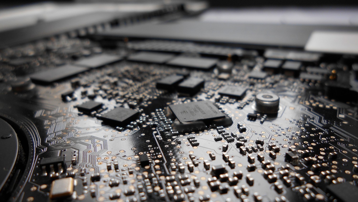
The high switching frequency of 1.6MHz of the controller allow also to use small components: in the picture there is a reduced size inductor, mounted on pads designed to carry on the higher ones. This left me some flexibility on performance analysis and experimentation.
Project summary: Glighter-S Power LED driver
- Technology: switching buck regulator
- Input voltage: 3V to 20V (note 1)
- Output voltage (LED Vf): 0.3V to 20V
- Sourced current: up to 1A (note 2)
- Size: 32mm x 21mm
- Efficiency: ~90% (note 3)
- Operating Temperature: -40°C to 60°C
- Safety features:
- Short circuit immune
- Open circuit immune
- Safe state (off) when no control is applied
- Control features:
- PWM control: voltage swing from <0.4V to >1.8V up to input voltage, max PWM frequency 5kHz
- Overtemperature protected
- It does not make the coffee, but the coffee made this. (note 4)
Note 1: active regulation starts from the forward LED voltage plus 0.6V. Full power is delivered from 4V on (device’s control voltages fully on)
Note 2: can be set by changing a resistor
Note 3: with one led with a forward voltage of 3V is 83%. 90% can be achived my using more than 3 LEDs in series.
Note 4: with caffeine.
On the back of the board there is a brief indication of what is summarized above:

Regarding safety, if the output is shorted, the regulator instantly lower the output voltage avoiding failures. With open circuit, as any buck converter with a sense resistor removed, the output raise as the input voltage due to the broken feedback loop, but with no damage on components: when connecting the LEDs back again, the regulation starts “immediately” avoiding LED damage. Smooth delayed start of few microseconds is implemented when powering the board with the enable already active, to avoid high inrush currents, stressing also less the LED avoiding high current glitches.
It can be dimmed with an analog signal or through a PWM wave up to 5kHz. A greater frequency is just filtered away. Another safety feature is that when PWM pin is left floating or the wire is broken, is equipped with a pulldown in order to guarantee a device shutoff with no misbehaviors. If no control is needed, just connect the PWM pin safely to the input voltage to turn it always on.
Wiring the LEDs
I wanted a very high power LEDs, but with a relatively low voltage, in order to try it also with low voltage batteries, lower than 6V. So I choose an LED with single diode chip, because when power LEDs have an high voltage (usually greater than 5V) is composed with multiple LEDs in series. My choice is a Luxeon Rebel LEDs, with a single diode, no series:

Each of these LEDs can take up to 700mA (1A peak), therefore I chosen the sense resistor on the board in order to achieve 700mA. I designed a board used as a satellite, mouting 4 LEDs, with the peculiarity of handling the thermal management of a global 9W LED lamp.
The LED board (a.k.a. satellite board) is straighforward: 8 pins, 4 anodes and 4 cathodes to drive each LED individually using 2 wires per LED connected to the driver. The A means anode (connect the +), K the cathode (connect the -). Below the RGBW LEDs soldered on the red, green, blue and white position.

On the back is mounted an heatsink capable of dissipating through natural convection up to 9W up to 40°C of ambient temperature. Bigger heatsink will extend the temperature range. But here the purpose is to have a small heatsink, and wasting time in my playground.

Wiring the driver
Here is shown the board connections used to test the LEDs and the driver.
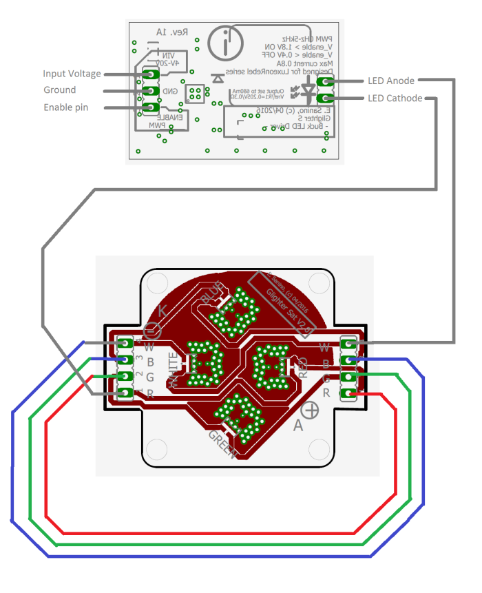
The input voltage was 20V from an old laptop power supply, the enable pin shorted to the 20V. I have connected 4 LEDs in series (one cathode on the next anode and so on), with a total forward voltage of around 12V, which means that in this configuration, the minimum supply voltage required was a bit higher than 12V, here 20V are provided. Since the leds in seried are dropping more than 3V (12V in total), the efficiency of the driver is near the 90%, because the ratio between internal losses and delivered power is lower.
The power absorbed is roughly 9W, I just can’t prove its light due to the exposure of the camera, but it is comparable of a white LED bulb of 10W commercially available.

Fun fact: these LEDs are also used in some Philips RGB lamps, with a similar thermal design of the PCB. That is somehow encouraging.
The schematics can be downloaded from Github.
Conclusion and next steps
There is no much else to say, but it works and it is a small accomplishment that allows me to play more with power LEDs, more easily than before, mainly because of the possibility to use, NOW, almost any power supply (from tablet’s charger, to laptop ones and any battery lying around).
Every microcontroller can drive these boards with no additional components. The absolute value on the pin higher than 1.8v will fully turn on the device. Any board, 5V, 3.3V or 1.8V can drive this module even with a low voltage logic I/O pin or even using an DAC. I plan to continue the improvement, and maybe design a control board in order to control these drivers with a small power low-profile set-up.

This project was featured on Hackday!
https://hackaday.com/2017/09/05/coin-sized-led-control/
Complimenti!
LikeLike
Thank you! 🙂
LikeLike